BBC Micro Music Masterclass
The musical interfacing potential of the BBC is so great that it well deserves a book devoted entirely to the topic. The user port, the one megahertz bus and the printer port can all accept and transmit digital information which can in turn be used to control synthesisers, Digital to Analogue and Analogue to Digital converters, relays and any number of similar devices. The on-board Analogue to Digital port can also accept analogue voltage information, such as that generated by a synthesiser or a tape recorder. It is beyond the scope of this book to go into the details of the design and construction of the sort of interfaces which would, for instance, allow the BBC to generate the voltages required to drive a synthesiser, or sample frequencies via a fast A/D converter. Other books and magazines can supply this information, a partial list of which can be found in the appendix. There are, however, a number of straightforward add-ons we can use or construct without embarking on a university electronics course. So let us begin by taking a look at the first of these, namely the common or garden joystick.
The humble joystick can be put to a number of other uses apart from the traditional and well documented one of controlling laser cannons or manoeuvring Pacmen. Before we come to use the stick to control elements of a program, however, we should start by RUNning the following test program.
 10
 20 REM *** Stick Test ***
 30
 40 MODE 7
 50 VDU23;8202;0;0;0;
 60
 70 REPEAT
 80  X%=ADVAL1DIV1024
 90  Y%=ADVAL2DIV1024
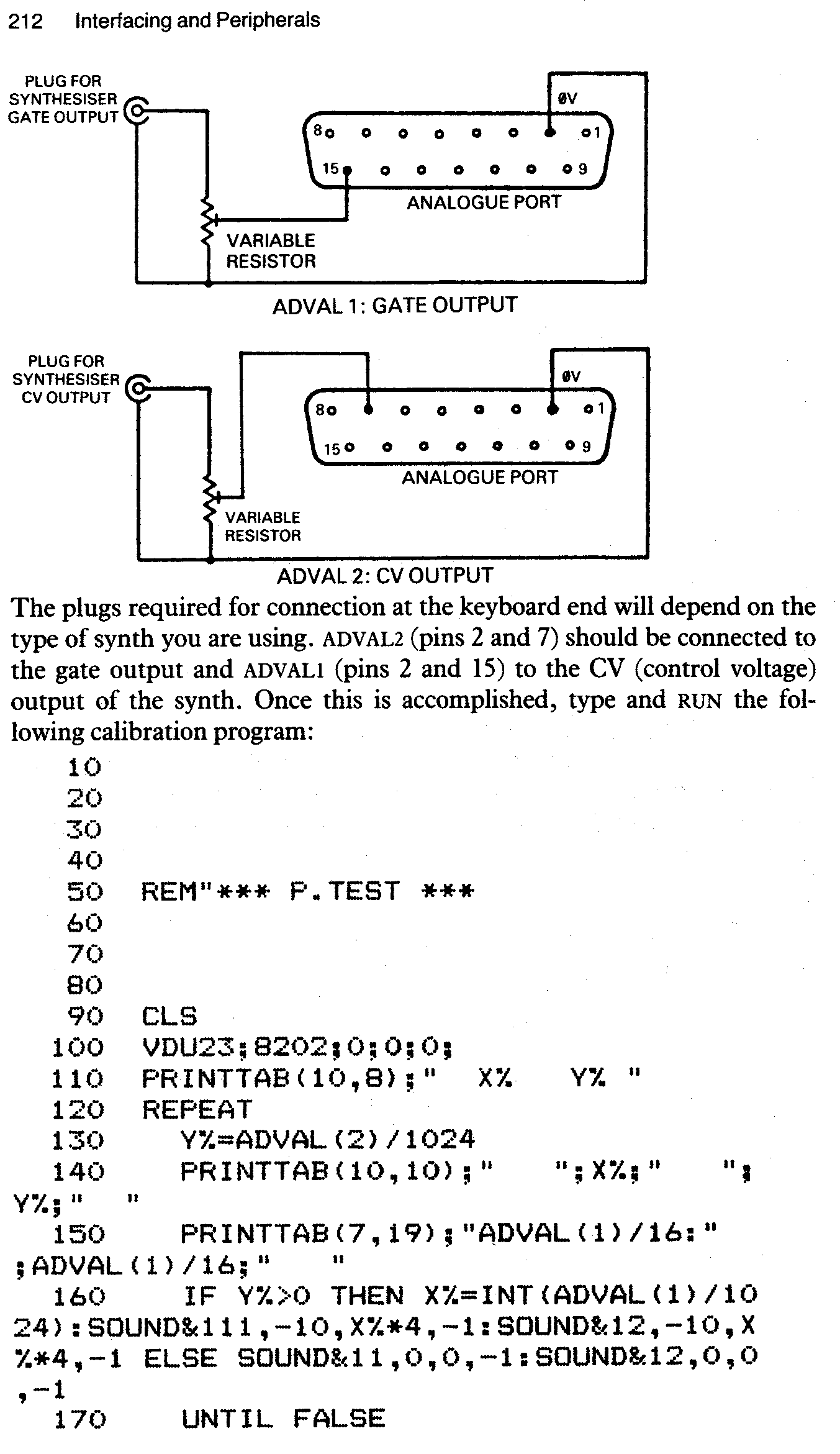
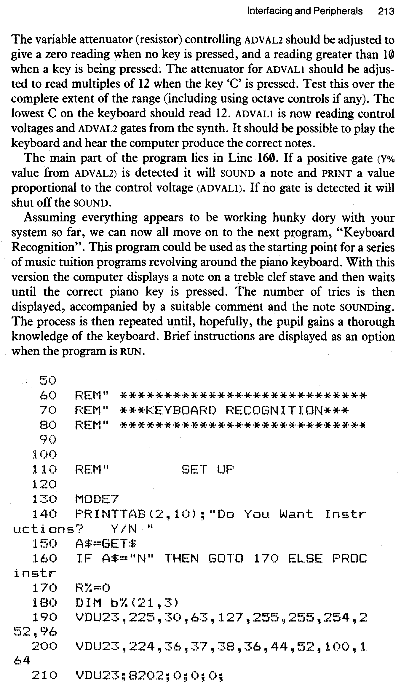
The variable attenuator (resistor) controlling ADVAL2 should be adjusted to give a zero reading when no key is pressed, and a reading greater than 10 when a key is being pressed. The attenuator for ADVAL1 should be adjusted to read multiples of 12 when the key C is pressed. Test this over the complete extent of the range (including using octave controls if any). The lowest C on the keyboard should read 12. ADVAL1 is now reading control voltages and ADVAL2 gates from the synth. It should be possible to play the keyboard and hear the computer produce the correct notes.
The main part of the program lies in Line 160. If a positive gate (Y% value from ADVAL2) is detected it will SOUND a note and PRINT a value proportional to the control voltage (ADVAL1). If no gate is detected it will shut off the SOUND.
Assuming everything appears to be working hunky dory with your system so far, we can now all move on to the next program, Keyboard Recognition. This program could be used as the starting point for a series of music tuition programs revolving around the piano keyboard. With this version the computer displays a note on a treble clef stave and then waits until the correct piano key is pressed. The number of tries is then displayed, accompanied by a suitable comment and the note SOUNDing. The process is then repeated until, hopefully, the pupil gains a thorough knowledge of the keyboard. Brief instructions are displayed as an option when the program is RUN.
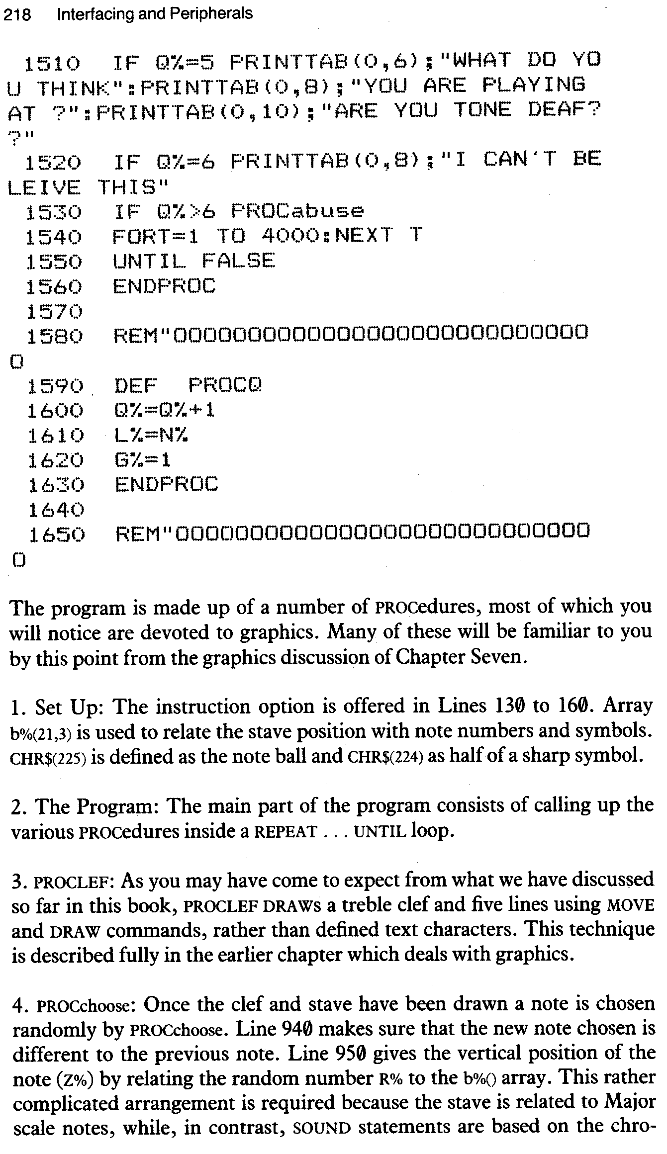
The program is made up of a number of PROCedures, most of which you will notice are devoted to graphics. Many of these will be familiar to you by this point from the graphics discussion of Chapter Seven.
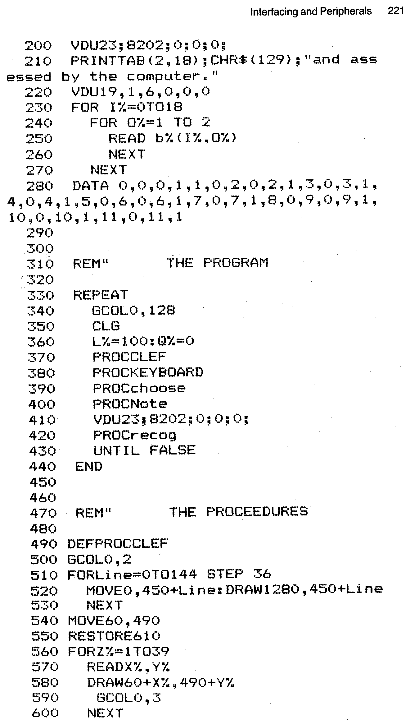
1. Set Up: The instruction option is offered in Lines 130 to 160. Array b%(21,3) is used to relate the stave position with note numbers and symbols. CHR$(225) is defined as the note ball and CHR$(224) as half of a sharp symbol.
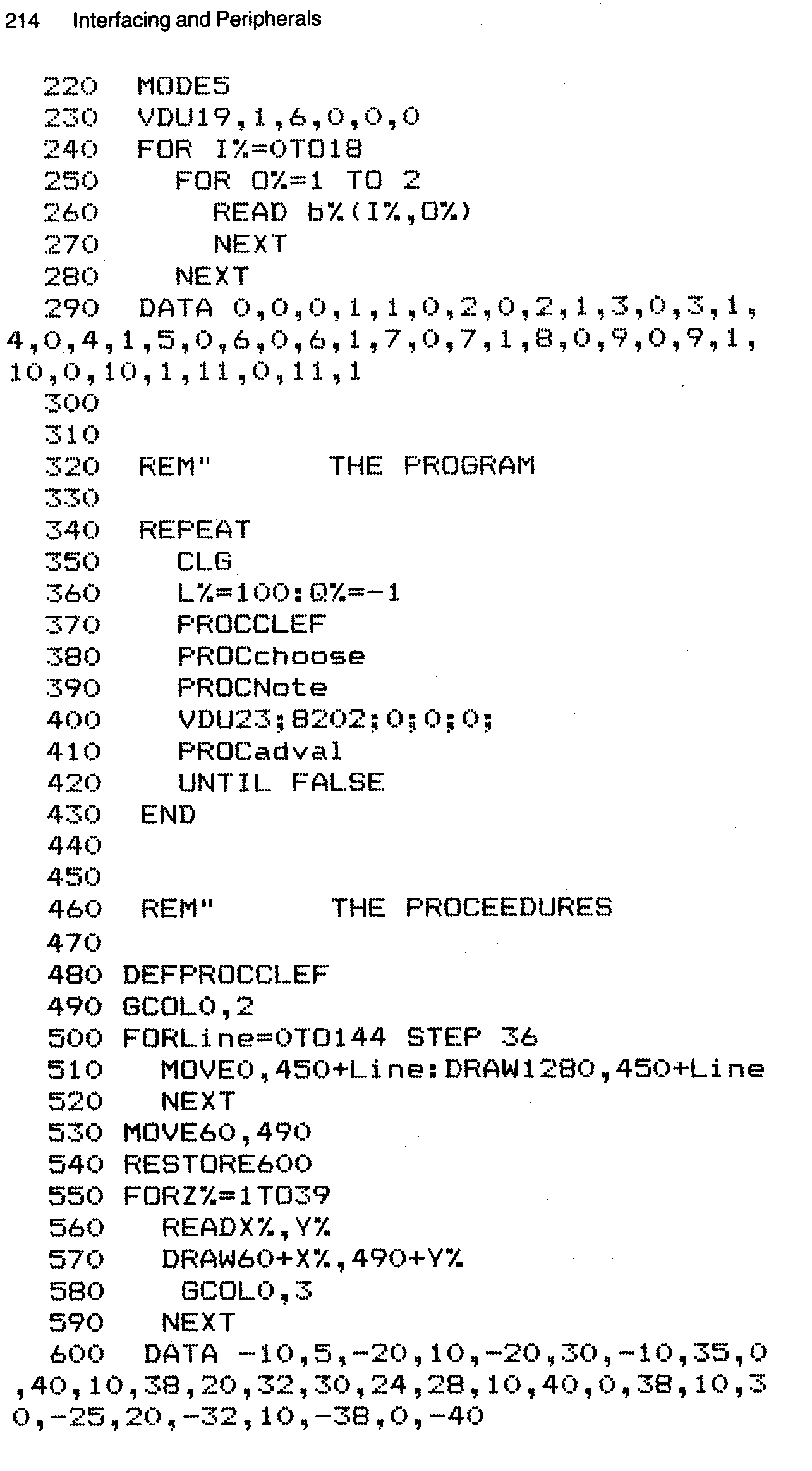
2. The Program: The main part of the program consists of calling up the various PROCedures inside a REPEAT... UNTIL loop.
3. PROCLEF: As you may have come to expect from what we have discussed so far in this book, PROCLEF DRAW s a treble clef and five lines using MOVE and DRAW commands, rather than defined text characters. This technique is described fully in the earlier chapter which deals with graphics.
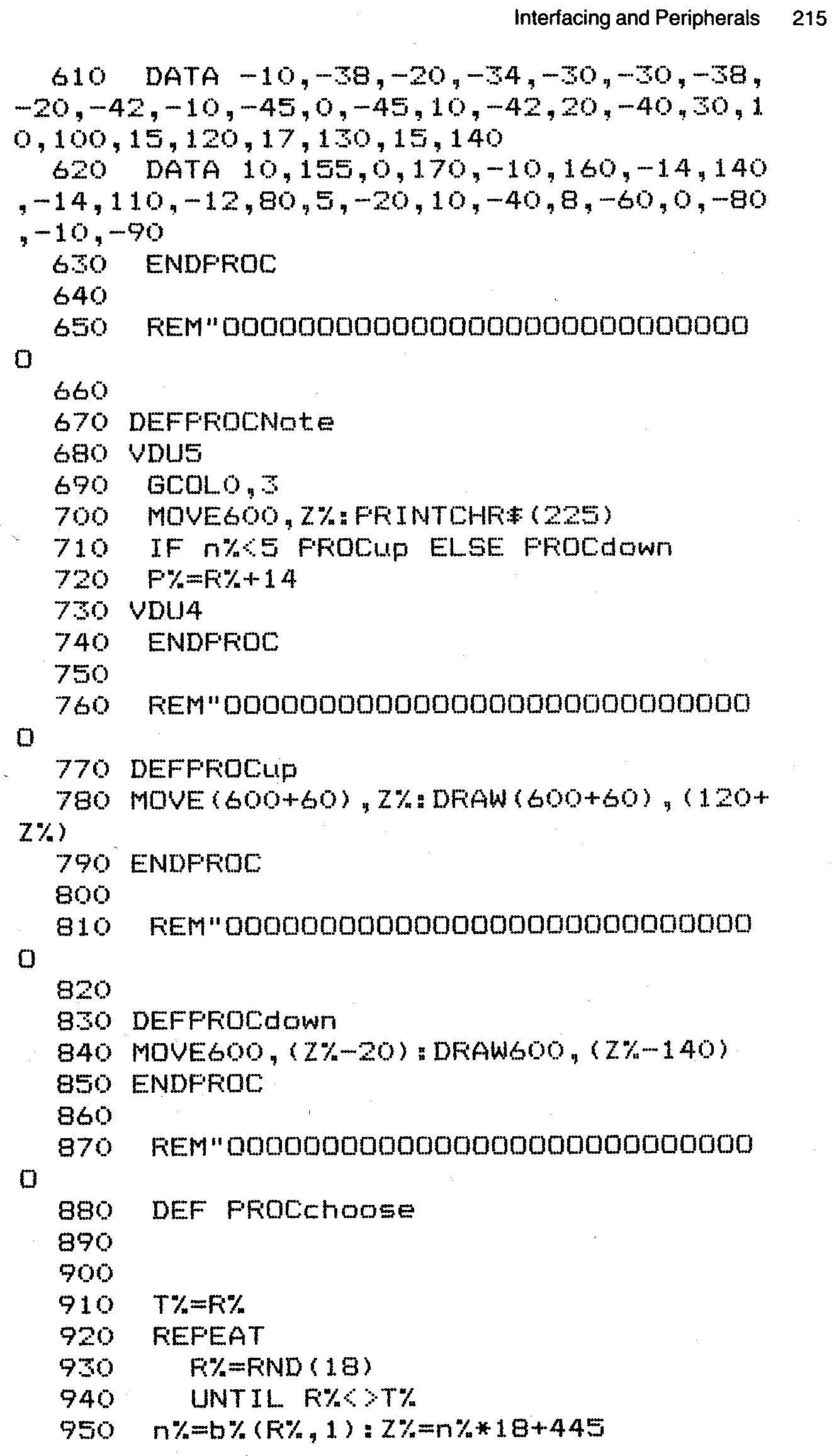
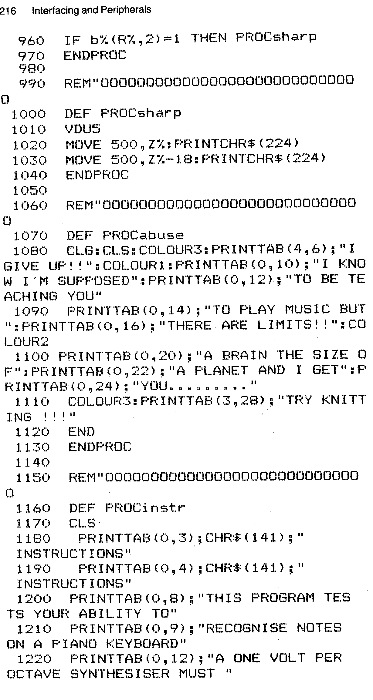
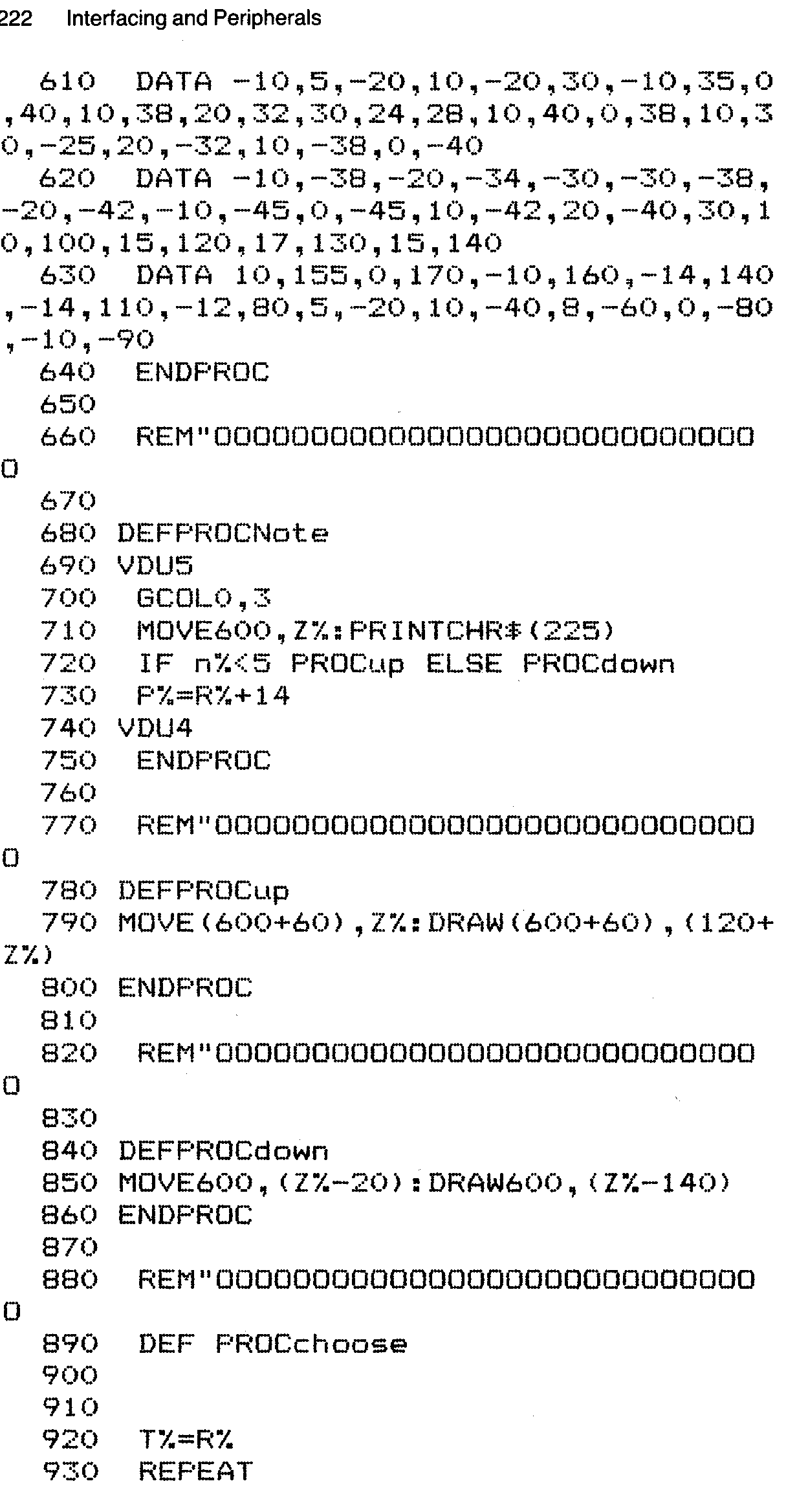
4. PROCchoose. Once the clef and stave have been drawn a note is chosen randomly by PROCchoose. Line 940 makes sure that the new note chosen is different to the previous note. Line 950 gives the vertical position of the note (Z%) by relating the random number R% to the b%() array. This rather complicated arrangement is required because the stave is related to Major scale notes, while, in contrast, SOUND statements are based on the chromatic scale. Some way must therefore be found to equate an eight note scale with a twelve note system. The b% array holds vertical step positions far every chromatic note. Line 960 then decides whether the chosen note is sharp or natural. It does this by examining the second dimension of the array. If we have b%(R%,2)=1 the program calls PROCsharp and a sharp is drawn at the correct position on the stave. The complete sharp is the two halves of the sharp stacked one on top of the other.
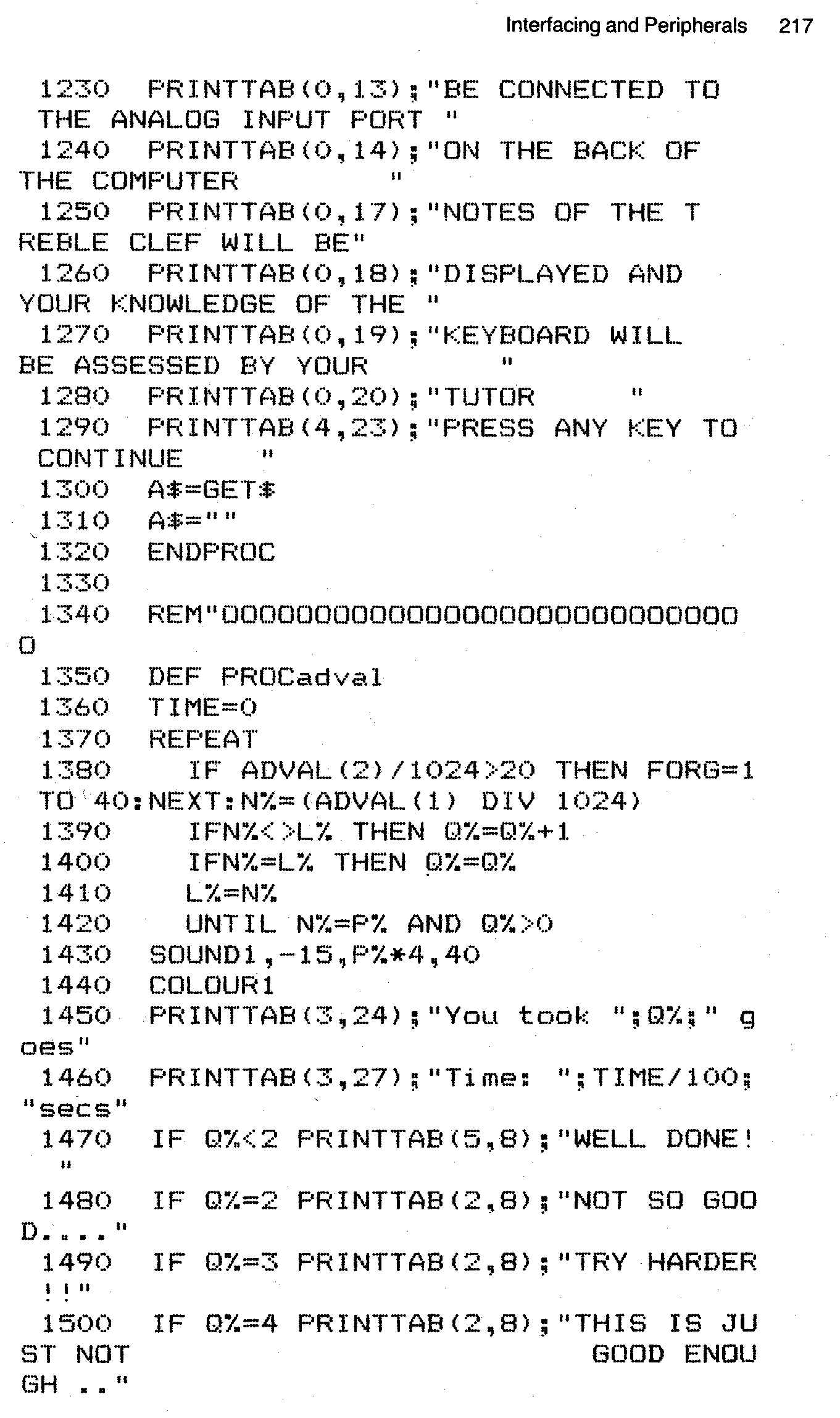
5. PROCNote. PROCNote not only PRINTs the note ball on the correct line or space, using VDU 5 to PRINT at the graphics cursor, but also DRAWs the stem of the note, either up or down depending on its position on the stave. Notes that are above the middle line are sent to PROCdown, the rest are sent to PROCup. These DRAW the stem relative to the note position variable Z%, using graphics techniques. Once the note has been displayed the analogue port input is used to test if the correct note is being pressed. ADVAL 2 tests for a keypress. If a key is pressed ADVAL 1 is read and its value compared with the previous value L% and the current note (P%=R%+14) derived from PROCchoose. Q% is used to count the number of attempts which have been made at guessing the correct note. When the correct note is chosen, so that N%=P%, it is SOUNDed in Line 1430, the number of attempts is PRINTed in Line 1450, the time in seconds is displayed and a comment, dependent on the number of goes, is PRINTed. If the number of goes is greater than six, the computer becomes frustrated and gives up!
Many changes and additions could be made to this program, depending on the use to which you wanted to put it. For example Tutor could be modified to play a note and make a comment after every attempt. In addition an overall score could be kept, and a time limit introduced, to add an element of competition. Different clefs and keys could also be tested. If a piano type keyboard was not available the standard alphanumeric keyboard could be used either to type in symbols or to be labelled as white and black notes.
One logical extension of the parameters of this program is to display groups of notes in phrases of differing timings. A horizontal scroll technique could even be used to test sight reading of fairly complex pieces of music. A sideways scroll can be accomplished by re-programming register 13 of the 6845 video controller chip. VDU 23 is used to bring this about. See the Advanced User Guide for more information on this subject. The inclusion of the next program was requested by my editor. It is a revised version of the program given above. It was pointed out to me that people not possessing a musical keyboard capable of interfacing with the Beeb might be a bit miffed at missing out on this whizzo program. Thus the revised program that follows, using many of the same PROCedures as the aforementioned program, has had a keyboard display included and the ability to accept input from the alphanumeric keypad.
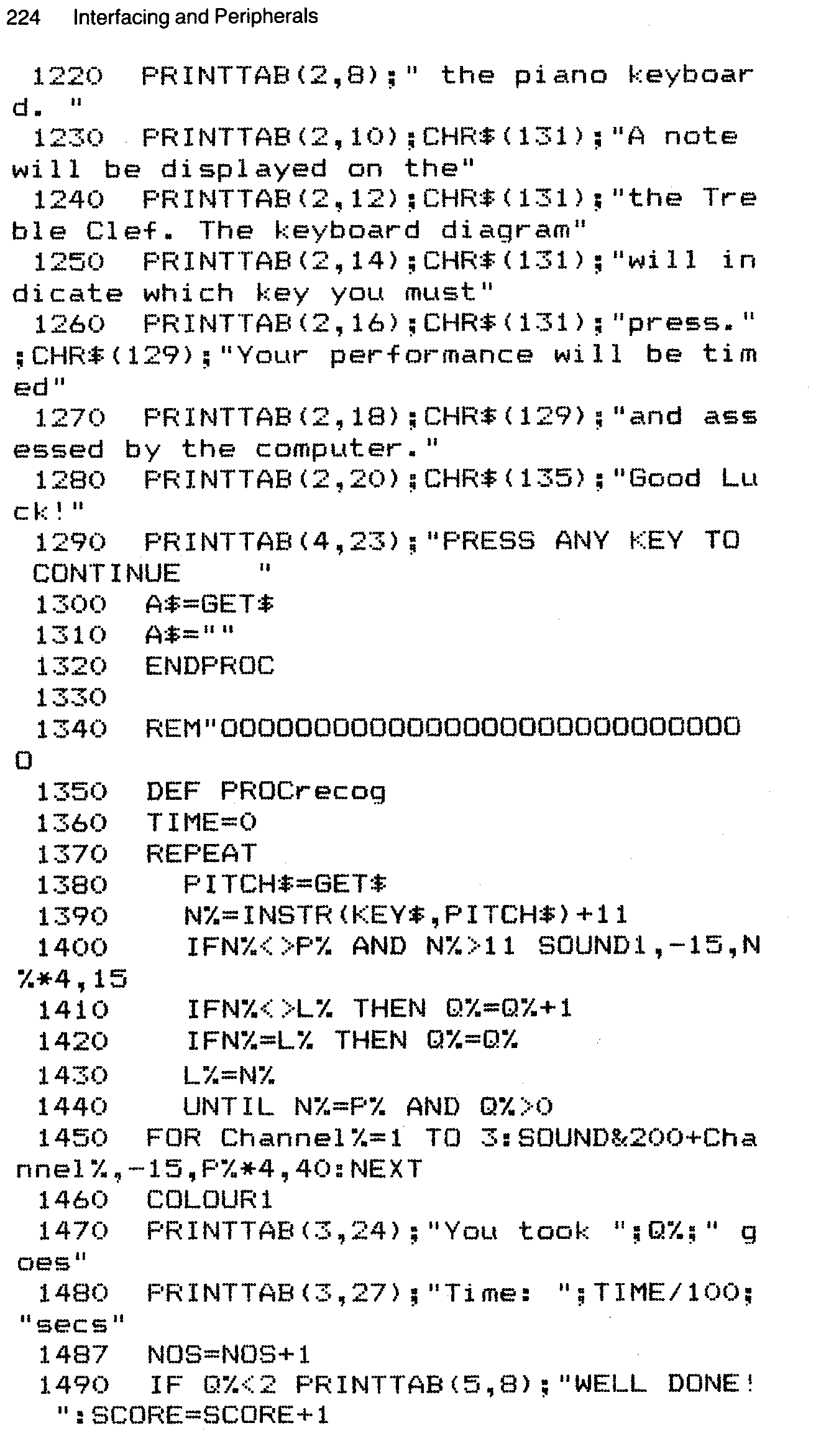
On RUNning the program you are first asked if you wish to see the instruction page, revised from that of the original program. Once into the test the screen displays a treble clef with a note on the stave. Underneath a piano keyboard is displayed with each key labelled with a letter from the qwerty... and 12345... key sequences of the computer keyboard.
The idea is to identify the note on the screen and press the corresponding key in as short a time as possible. If an incorrect key is pressed that note will be SOUNDed quietly and the note will continue to be displayed. If the correct note is pressed the note will SOUND loudly and a message will be displayed on the screen along with the time you took. If you got the note right first time the message will be congratulatory, otherwise...
This process will continue until either you fail to get the correct note so many times that the computer gives up, or you press
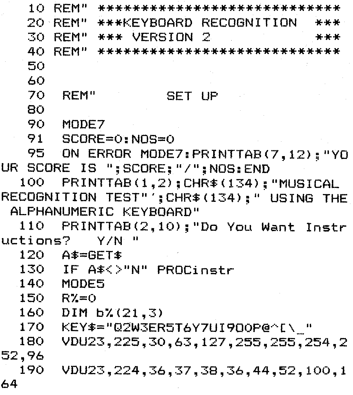
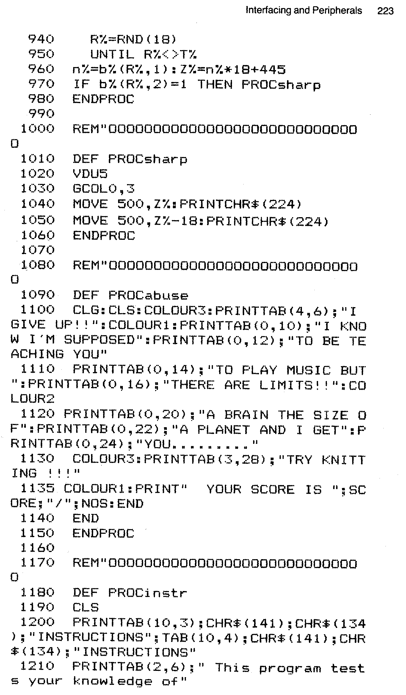
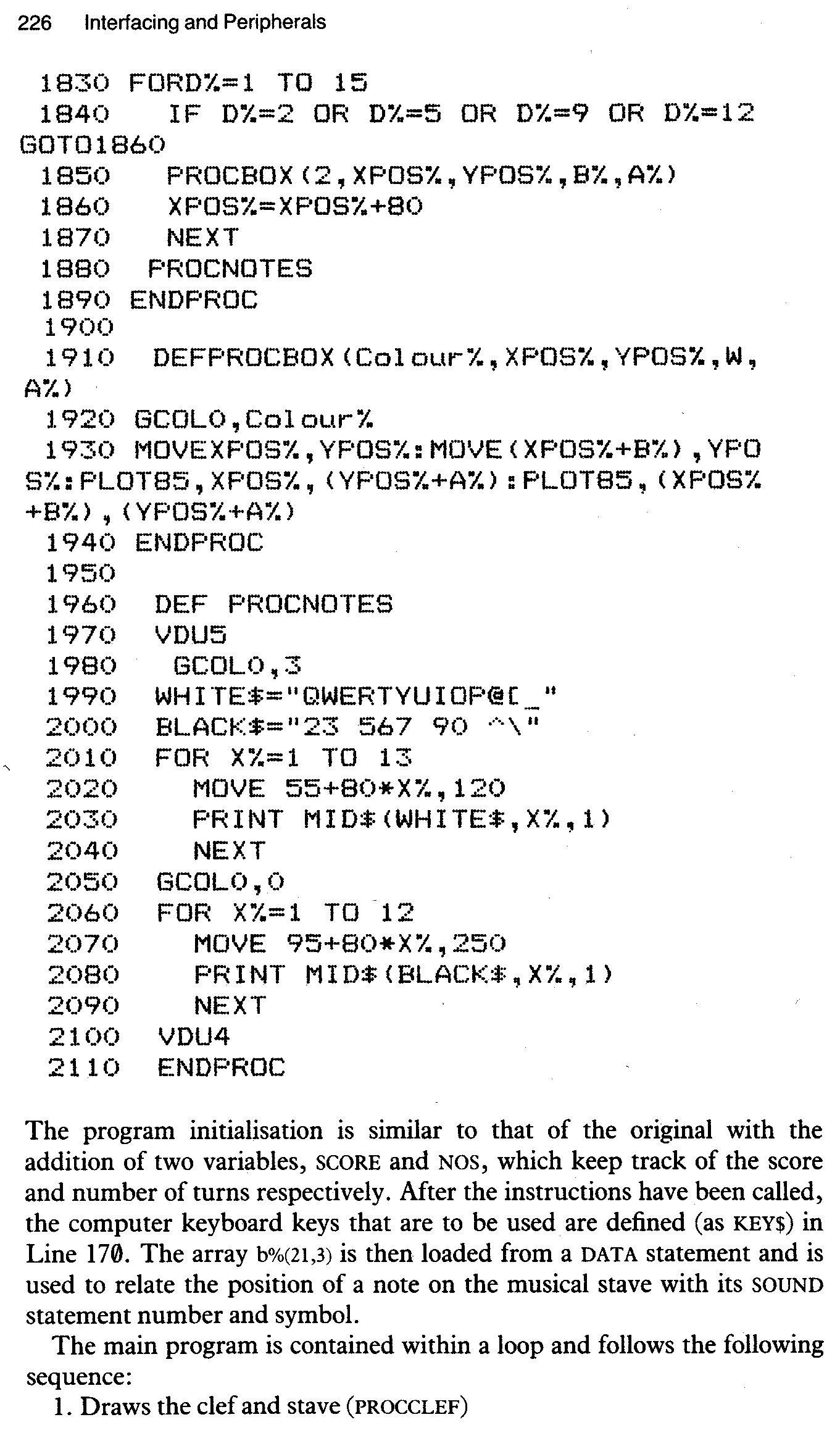
The program initialisation is similar to that of the original with the addition of two variables, SCORE and NOS, which keep track of the score and number of turns respectively. After the instructions have been called, the computer keyboard keys that are to be used are defined (as KEY$) in Line 170. The array b%(21,3) is then loaded from a DATA statement and is used to relate the position of a note on the musical stave with its SOUND statement number and symbol.
The main program is contained within a loop and follows the following sequence:
1. Draws the clef and stave (PROCCLEF)
2. Draws the keyboard (PROCKEYBOARD)
3. Randomly chooses a note (PROCchoose)
4. Draws the note on the stave (PROCNote)
5. Waits for input then reacts to answer (PROCrecog)
PROCCLEF draws the treble clef using graphics techniques described earlier. PROCNote positions and draws the note on the stave and calls either PROCup for an upward stem or PROCdown for a downward stem. PROCchoose randomly chooses the next note, making sure that it is different to the previous value. PROCsharp draws a sharp symbol in front of the chosen note if appropriate.
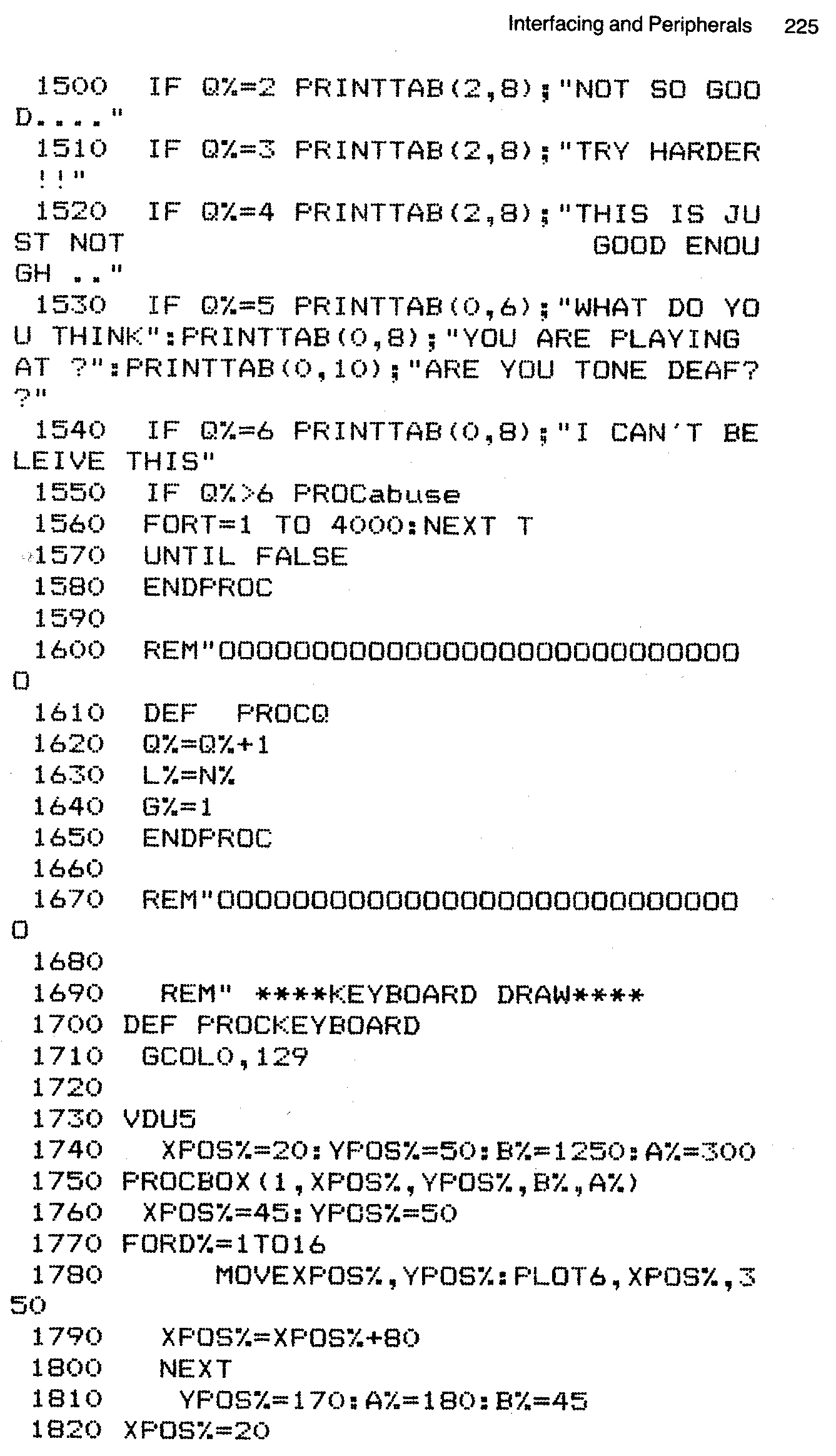
PROCabuse is called when the computer decides there is no hope for you as a piano player. In addition to berating you over your musical ability it also displays your overall score. PROCinstr contains your initial instructions.
PROCrecog differs from the PROCedure in the earlier version of the program in that instead of using the ADVAL function to test for a keypress on a keyboard attached to the analogue port, in this case GET$ is used to give us a value for PITCH$, which is converted to a numerical value, using INSTR, in Line 1390. N% is then compared with the computers chosen value P%. The computers reaction to your attempts depend on the value of Q%, the number of goes.
PROCKEYBOARD is concerned with drawing and labelling the piano diagram. It uses a series of different sized boxes to make up the keyboard. Since we are in a four colour mode the choice of colours for this purpose is somewhat limited. Due to the inconsistent pattern of piano keys PROCBOX must be called a number of times. PROCNOTES labels the keys using two strings for the white and black keys. Spaces are included in BLACKS to take account of the missing notes between B and C and between E and F.
Common peripheral devices for the BBC microcomputer include cassette recorders, disc systems, monitors and printers. The currently available models of printers and monitors are so varied that any comments I could possibly venture would only backfire immediately since chances are that they would only apply to a small percentage of users. For this reason I will leave the interesting subject of printer graphics to others! Many commercially available printer drivers will give hard copies of our music graphics.
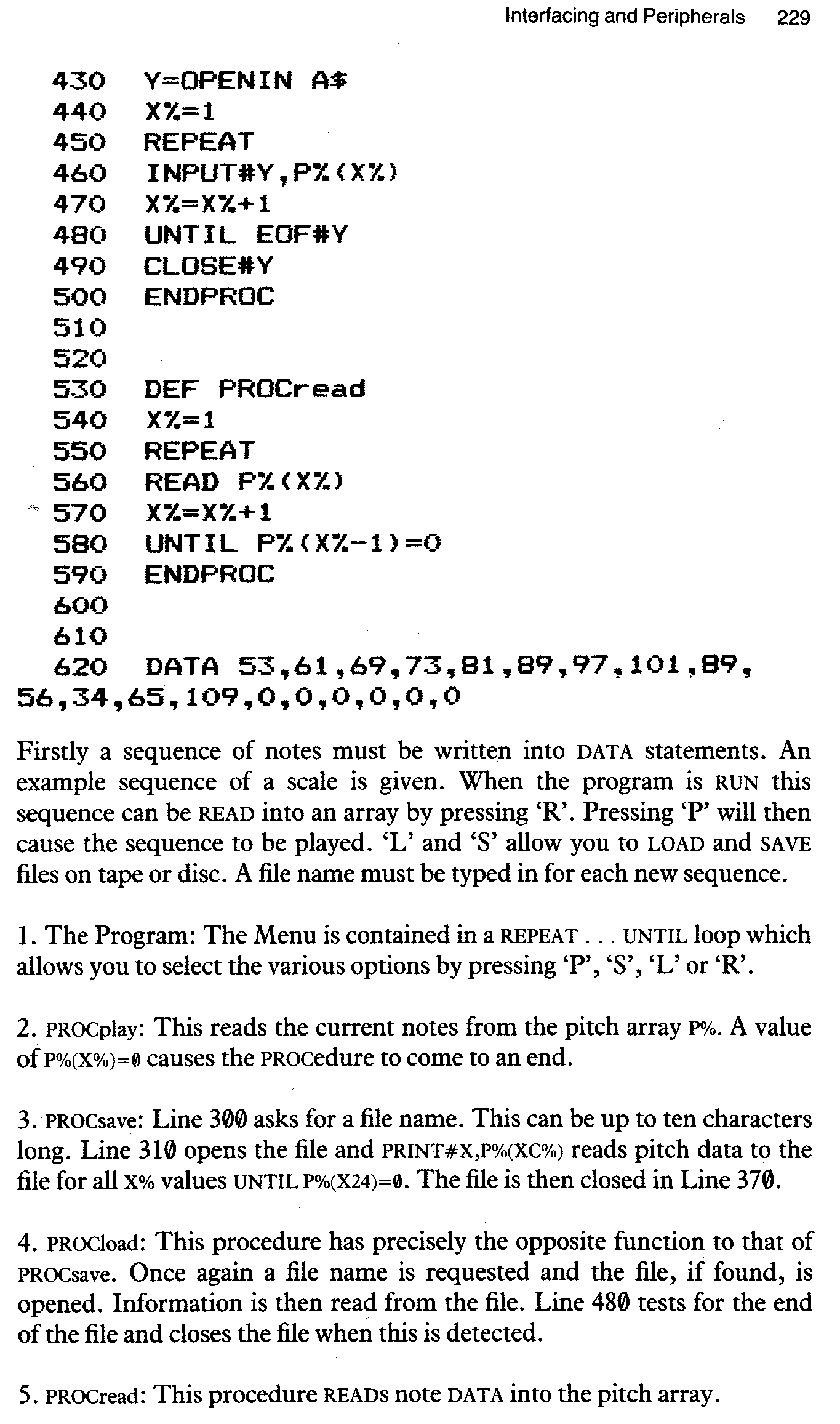
Cassette recorders and disc systems can be used for recording DATA RS well as complete programs. We can therefore save our musical compositions in files separate from the program which will play them back. The BBC is so designed that the same set of commands will allow us to create both cassette and disc files. The program Files indicates how this might be done in the simple case of a note sequence.
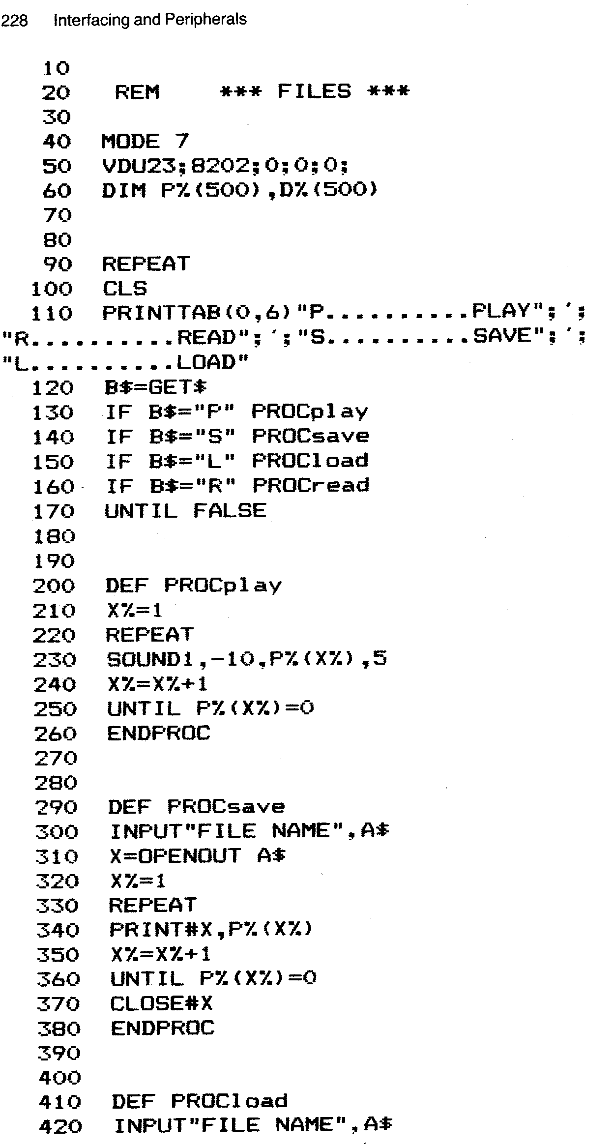
This is a very basic example of file handling. If you were interested in adapting it for practical use, obviously a number of refinements would have to be added. For instance, as it stands, file names larger than ten letters would cause the system to crash, as would a file name which could not be found, for whatever reason, when loading.
There is one other external device that can be connected to the BBC. Note, however, that one disadvantage to embracing the device lies in the fact that this does involve opening up the case of the computer and having a quick root around inside.
The BBCs sound chip drives the internal speaker directly, without utilising any external form of amplification. This means that the volume levels which are attainable from the computer are not exactly ear-splitting. If this situation suits you down to the ground then you need read no further. If you have ever felt the need to play your latest computer composition to the whole street, however, then this is how you go about doing it. Do not attempt this unless you are confident of your mechanical and soldering skills, however, as it means opening up your BBC Micro.
Since most of you probably possess some form of amplifier and speaker arrangement, be it a Quad Hifi or a Ghetto Blaster, I will not describe the construction of an amplifier! I will simply indicate how your BBC can be connected to one of these devices, either for live performance or direct recording into a tape recorder (i.e. not via a microphone).
The parts which you will require for this modification include a length of two-core wire (about a foot) and a socket (the exact type is entirely dependent on what you wish to hook it up to).
Solder the two cores at one end of the wire length to the socket in preparation for connection to the computer. The computer case can be removed by unfastening four Philips screws, the two underneath nearest the front and the two on the back of the BBC. It is also necessary to remove the keyboard by unfastening two additional screws underneath the computer. This done, the keyboard can now be removed entirely by carefully unplugging the multi-pin connecting cable and speaker lead. Once you have done this, the speaker can be clearly seen on the left of the keyboard.
Unfasten the speaker from the board by removing the restraining screw and solder the free ends of the two-core wire to the speaker connection. The socket end of the cable can be fed out through the Econet port or the hole in the computer casing which is to be found next to it. Now reass-emble the computer so that you can connect the new sound output to the tape or tuner input of your amplifier.
A more sophisticated arrangement would include an internal/external sound switch as well as a volume control, but I will leave you to either work this out for yourself, or find someone who can! This type of connection will also allow you to make good quality recordings of your own computer compositions.
It is possible, using the analogue input port, to synchronise music programs to an external clock such as that provided by a drum machine or sequencer. This external clock would replace whatever timing loops were contained in the program and allow, say, the Drum Program to be run from a synthesiser/sequencer such as the Roland SH 101 or Bassline or another drum machine.
To accomplish this we must first connect a few simple electronic components to the analogue input as shown in the following diagram:
TRIGGER INPUT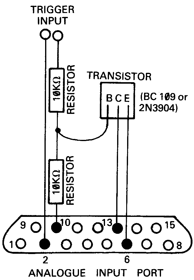
An NPN type transistor is used, such as the BC109 or the 2N3904. Other components include two 10Kohm resistors and a connector of your choice. The transistor should be labelled with the letters B C E (though not necessarily in that order) and must be connected in the fashion shown. The following PROCedure (PROCsync) can be then used to sense the incoming trigger pulse:
100 REM SINGLE TRANSISTOR SYNCHRONISER
110
120 REPEAT:PROCsync:VDU7:UNTIL FALSE
130
140 DEF PROCsync:REPEAT:UNTIL(16 AND ?&FE40)=0:ENDPROC
The above program allows you to test if your circuit is working correctly. The computer should ring its bell every time it senses an input. Once you have determined that your interface is operational, PROCsync can be incorporated into a program. For instance in the drum machine program PROCsync could be used to move through the sixteen steps rather than being controlled by the computer via tempo.
The circuit should be capable of sensing any trigger whose voltage exceeds 2 volts. Other factors that affect how well the circuit performs include the length of the trigger pulse and the polarity. It is up to you to experiment with the suggested set up to make it work under your particular conditions. At this point we must leave our final topic, as it becomes more a matter for the circuit-builder than the budding micro-musician.