HCR ELECTRONICS
CONTENTS
1. INTRODUCTION
2. INSTALLATION
4.1 OPTION 1 COPY ROM TO BUFFER
4.2 OPTION 2 BLANK CHECK ROM
4.3 OPTION 3 PROGRAMS FROM BUFFER
4.4 OPTION 4 VERIFY EPROM AGAINST BUFFER
4.5 OPTION 5 LIST / EDIT BUFFER
4.6 OPTION 6 SAVE BUFFER TO FILE
4.7 OPTION 7 LOAD FILE TO BUFFER
4.8 OPTION 8 CREATE BBC ROM IMAGE
4.9 OPTION 9 RETURN TO BASIC
6. CREATE BBC SIDEWAYS ROM IMAGE
8. PRODUCING PROGRAMS FOR BBC SIDEWAYS ROMS
The MICRON PLUS EPROM PROGRAMMER from HCR ELECTRONICS is designed to handle a variety of EPROMs currently available.
The programmer will operate on the BBC model 'B', model 'B PLUS', and the MASTER SERIES and requires a machine operating system series 1.0 or later.
Software to drive the programmer is provided on EPROM providing a menu driven ROM resident easy to use set of routines. This EPROM must be fitted into one of the available sideways ROM sockets provided.
Included are all of the EPROMs specified for use on the BBC computer including 32K devices (27256) and 64K devices (27513). The latter type is used on the MASTER series in the external cartridge and is organized as 4 addressable pages of 16K Bytes.
32K EPROMs may be programmed in one pass. This is achieved by the provision of 16K of RAM within the programmer. The programmer utilises the BBC RAM from &2000 to &6000 as a buffer to hold ROM images together with the 16k of RAM in the programmer and forms a 32K long buffer. This buffer can be written to from EPROM, loaded from file, saved to file or arranged byte by byte using the built in FULL SCREEN EDITING facility.
All of the usual features of a programmer are provided including: –
Additionally provision is made on certain types of EPROM to alter the program potential to cater for 'New Technology' Chips using lower programming voltages.
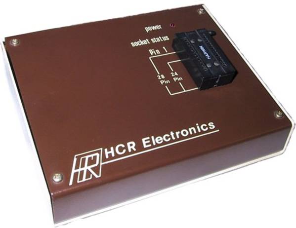
The programmer is mounted in a two tone case with a ZIF (Zero Insertion Force) socket mounted on the sloping front panel. A length of ribbon cable terminated in an I.D.C. 34way socket emerges from the rear of the programmer and is inserted into the 1MHz bus connector on the BBC computer. A mains lead is provided for the built in power supply.
The programmer has NO SWITCHES as all variables are taken care of with solid state switches and relays controlled by the operating software.
This includes all HT voltages and the ZIF socket is placed in a high impedance condition on reset. At the completion of any operation all power is removed from the EPROM thus creating a non-hostile environment for inserting and removing EPROMs. (The socket status is also monitored by a front panel LED).
LOADING AND SAVING TO FILE is taken care of and provision is made for specifying the address in buffer for loading to, and the start and end address when saving as well as default settings.
When unpacking the MICRON PLUS PROGRAMMER an EPROM containing the operating software will be found. This must be handled with care to ensure that pins do not become bent. To avoid possible static damage it is best if you have discharged yourself of any accumulated charge by touching an earthed object such as a water or gas pipe.
The first step is to fit a mains plug to the end of the cable supplied.
This should be a 13 Amp plug FITTED WITH A 3 AMP FUSE.
IT IS NOT ADVISABLE TO FIT A FUSE OF A LARGER RATING.
The connections are as follows: —
| BROWN | LIVE |
| BLUE | NEUTRAL |
| GREEN / YELLOW | EARTH |
The supplied EPROM must be fitted into a spare sideways ROM socket inside the BBC computer and this demands that the cover is removed.
On the MASTER series Cartridge sockets are fitted and the EPROM may be fitted into one of these by obtaining a spare cartridge from ACORN or selected dealers. Alternatively the EPROM may be fitted into the spare 16K ROM socket inside the master. There are two other sockets available in the MASTER but using these will result in loss of sideways RAM and is not therefore recommended.
The instructions for removing the top cover are common to the BBC model 'B', and model 'B PLUS'. Remove two screws marked FIX from the underside of the case and two from the rear of the case near the ends. On the MASTER all four screws are fitted in the base. Lift off the top cover and place to one side.
On the BBC'B' The keyboard must be removed to gain access to the ROM sockets and is secured by two or three screws and nuts depending on the model. It is not necessary to remove the keyboard from the 'B plus' or the MASTER.
On the BBC'B' the sideways ROM sockets are on the right hand side of the main circuit board and nearest the front of the machine. They are labelled IC52, IC88, IC100 and IC101. IC51 is the operating system ROM and must remain in its socket. The EPROM supplied may be fitted into any one of the four ROM sockets that are spare however if the machine is to power up in BASIC then it should be fitted to the left of the BASIC ROM.
Ensure that the EPROM legs are straight before insertion and check that the half moon cut-out notch at one end of the EPROM is facing the rear of the computer. Press the EPROM fully home and check that no pins are outside the socket or tucked under the EPROM.
The B plus has its ROM sockets in a group of six on the left of the main board and near the back. They are marked (rear row left to right) IC71, IC68, IC62, and (front row left to right) IC57, IC44, IC35.
IC68 and IC62 are taken up with the DFS and BASIC/MOS but any of the remaining may be used for the programmer software.
As discussed earlier the MASTER has one 16K ROM socket and is situated on the right hand side of the main board in the middle of a vertical row of sockets. This socket is labelled IC27. If one of the other two sockets is considered then please refer to the MASTER reference manuals. If the cartridge socket is used then refer to instructions supplied with the cartridge.
Replace the keyboard if it was removed and switch on the computer. Type
*HELP <RETURN>
and the computer should respond with a list of ROMs.
Check that MICRON PLUS EPROM PROGRAMMER 1.30 appears in the list.
EPROM
If all is well replace the computer top cover.
The PROGRAMMER is connected to the computer by plugging in the thirty four way connector on the end of the flat ribbon cable into the 1MHz bus connector. This can be found beneath the front of the machine and is the second connector from the right. Take care that the socket is inserted the correct way round. (A polarising bump on the socket should mate with a corresponding cut-out in the plug beneath the computer).
As the software is the currently selected language extensive use is made of pages 4, 5, 6 & 7 reserved for languages.
Zero page locations from &70 to &82 are also used.
The ROM image buffer runs from &2000 to &6000
JIM addresses used are &FCC0 to &FCC7 inclusive.
FRED addresses are not used.
The MICRON PLUS EPROM programmer is capable of' programming the following types of EPROM:-
| TYPE | CAPACITY | PROGRAMMING VOLTAGE |
| 27513 | 64K (IN FOUR 16K PAGES) | 12.5V |
| 27512 | 64K | 12.5V |
| 27256 | 32K | 12.5V |
| 27128 | 16K | 21V |
| 2764 | 8K | 21V |
| 2732 | 4K | 25V |
| 2716 | 2K | ** (see note below)** 25V |
| 2564 | 8K | 25V |
| 2532 | 4K | 25V |
| 2516 | 2K | 25V |
NOTE: ALL of the above ROMs are SINGLE 5 Volt supply EPROMs. In the case of the 2716 most manufacturers make a single rail type but TEXAS make a triple rail version of this type no. (TMS2716) and therefore cannot be programmed on this machine. However TEXAS make a single rail equivalent to the 2716 and is type no. TMS2516 CMOS equivalents may also be programmed.
The NORMAL PROGRAMMING voltages for each type is shown and is the default voltage selected when programming. However as newer versions of some chips use lower programming voltages and are usually distinguished with a suffix 'A' in their type No. Normally a suffix 'A' device uses the next standard programming voltage below that of a standard device, i.e. a type 2732 will use 25V but a 2732A will use 21V, a type 27128 will use 21V but a 27128A will use 12.5V.
For selected types in the list above the programming voltage can be changed from standard, this is done by pressing CONTROL and 'V' together and will cycle the programming voltage (VPP) through the values available, i.e. 12.5V, 21V & 25V.
IF EVER THERE IS ANY DOUBT as to programming voltages PLEASE CONSULT EPROM MANUFACTURERS DATA SHEETS.
IT IS ABSOLUTELY IMPERATIVE THAT THE CORRECT PROGRAMMING VOLTAGE IS USED, FOR A GIVEN DEVICE. IF THE VOLTAGE IS TOO HIGH THE EPROM WILL ALMOST CERTAINLY BE DESTROYED.
For 8K and larger capacity series 27 devices a fast algorithm is implemented as standard. This is recommended by most manufacturers to reduce programming times particularly on larger capacity EPROMs.
This is achieved by programming with 1-millisecond pulses and checking to see if that location is programmed. If not then the 1-millisecond pulse is repeated until that location verifies whereupon a pulse width that is a function of the number of pulses up to then is additionally applied. If 15 pulses have been applied without success then the programmer stops and reports the failure point. If all is well the programmer steps to the next ROM location and repeats the sequence. When all locations are programmed then the programmer automatically VERIFIES the contents of the EPROM against the buffer and reports if a failure occurs. The above is carried out with VCC set to 6V in accordance with manufacturer's recommendations.
The above algorithm varies slightly for the 64K devices and is correctly implemented by the programmer.
With the programmer ribbon cable plugged into the computer and the mains plug connected check that the LED marked POWER is on. If not check the mains supply to the programmer. Type:
*EPROM <RETURN>
from the keyboard and after a small delay while the buffer is cleared a title page should appear together with a list of EPROM types supported.
SELECT THE EPROM TYPE BY SELECTING 1 TO 9.
The main menu will then be displayed.
At the top is displayed the EPROM selected, programming voltage and algorithm selected (FAST or SLOW i.e. standard 50ms pulse). Whilst in main menu mode the programming voltage may be altered from the default value as required by pressing CONTROL and V together.
DO NOT insert an EPROM until the device type has been selected and the main menu has been entered.
To reselect the device type return to the title menu FROM THE MAIN MENU by pressing <ESCAPE>.
At this stage the SOCKET STATUS LED SHOULD NOT be illuminated.
EPROMS MUST ONLY BE INSERTED AND REMOVED WHEN THIS GREEN LED IS NOT ILLUMINATED.
This LED will normally be extinguished on BREAK and at the completion of the various menu routines.
A ZIF (Zero Insertion Force) Socket is fitted on the front panel to make it easy to insert and withdraw EPROMs without damaging the pins. The EPROM should be inserted with the lever vertical. The EPROM is locked into position by pushing the lever to the right and downwards. To remove EPROM simply return lever to vertical position and lift out EPROM.
When 24-pin EPROMs are used they must be inserted to the bottom of the ZIF socket i.e. the top two pins nearest the lever on each row will remain empty
When in the main menu a star command may be entered from the keyboard by typing *<command> in the usual manner. When return is pressed the screen is cleared and the command is executed reporting errors in the usual way. When finished the main menu can be returned to by pressing any key.
The contents of an already programmed EPROM may be read programmers buffer. The RAM can then be saved to file with modified with option 5 or programmed into a new EPROM.
After selecting OPTION 1 a “CURRENT SETTING DISPLAY” is shown at the head of the screen.
Below is a prompt
GO?Y/N.
Answering with anything other than “Y” will abort the operation and return you to the main menu. Remember the buffer will be overwritten by this option so ensure that anything previously occupying the buffer that is required has been saved to file.
After pressing “Y” the message “PLEASE WAIT” will appear for only a second or two followed by the message “ROM COPIED TO MEMORY”
CHECKSUM= XXXXXX
Where XXXXXX is a six digit hexadecimal number corresponding to the sum of all the bytes in the EPROM. This may be used in future when comparing EPROMs or for checking data integrity in already programmed devices. After pressing any key to return to main menu the buffer contains the contents of the EPROM. The EPROM may now be removed from its socket.
In the case of 27513 64K EPROMs these are programmed and read one 16K page at a time and you will therefore be prompted for the page to be read in the range 0-3
27512 64K EPROMs have to be programmed in two passes as the max buffer size is 32K therefore operations on these EPROMs will prompt for the upper or lower address space to be selected.
Selection of this option is similar to 4.1 except that the contents of the EPROM are read and then checked to ensure that each location is set to &FF. THIS OPERATION DOES NOT CORRUPT THE BUFFER MEMORY.
An EPROM is considered blank if all bits in any location are set to one, this corresponds to &FF and is the state of a new 'UNBLOWN' EPROM. Programming any location is the process of setting one or more bits low, the opposite process of returning bits set to zero to 1 can only be achieved by exposing the EPROM to a source of ultraviolet light through the quartz window.
If the blank check fails then the blank check will terminate and display the location at which the ROM failed. A warning alarm will sound which can be stopped by pressing a key. If this happens the actual contents can be inspected by copying into RAM and using the buffer listing option.
Refer to section 5.
Selection of this option is similar to 4.1 except that the contents of the EPROM are compared byte for byte with the contents of the RAM. If the test fails then the first location that failed is displayed. The warning alarm will also sound.
THE CONTENTS OF THE BUFFER ARE NOT CORRUPTED BY THIS OPTION.
If the comparison is successful then the checksum is calculated and can be compared with the correct checksum (if known). This option may be selected at any time to compare a suspect EPROM with a disc copy of the ROM image after loading that image from disc. After programming using option 3, this option will be automatically selected to complete the program / verify sequence.
When OPTION 5 is selected a display is obtained of the contents of buffer memory. The buffer is 32K long and runs from &0000 to &7FFF. The left hand column displays the buffer address in hex corresponding to the first byte in the adjacent row of 8 two digit hex numbers. To the right of this field is a row of 8 characters and corresponds to the ASCII equivalent of the previous hex digits. If the number is not an ASCII character then a full stop is displayed instead. Unless option 1 has been used or the buffer loaded from file then all buffer locations will be at &FF. The length of the buffer always stays the same regardless of the amount needed to hold any given EPROM.
Any location may be edited from the keyboard by moving the flashing cursor to that location with the arrow keys and typing in two hex digits. The ASCII display is automatically updated after this operation. Alternatively by pressing TAB the flashing cursor will move to the ASCII display and location changes may be effected by typing ASCII characters directly from the keyboard. This is useful for editing text. The hex display is automatically updated during ASCII entry.
Movement is made through the buffer memory by use of the arrow keys and shifted up and down arrow keys to move in larger steps through the memory. To move to any location quickly the COPY key may be pressed when in hex entry mode. You will be prompted to enter a four digit hex number to move to. After pressing RETURN the display will be restored. Any attempt to move beyond the buffer limits will result in the buffer 'hitting the end stops' and not moving beyond.
At any time the entire buffer may be cleared to &FF by pressing CONTROL and C together. As this may destroy valuable data you are asked for confirmation before execution.
A print out of the buffer contents may be obtained by pressing CONTROL and P together. You will be prompted to enter start and finish addresses for the printout. The print routine will hang if a printer is not connected. The print routine will output correctly to EPSON compatible printers.
Serial printers may be configured via star commands from the main menu.
To exit prematurely press the BREAK key. Do not press escape as this may produce unpredictable results.
The EDITOR is a very useful facility since all EPROM copying verifying and programming is achieved via the buffer memory.
This option allows the contents of the buffer memory to be saved to file. On selection you will be prompted to enter a file name. This may not be more than seven characters long but can additionally include drive and directory if required. On pressing RETURN you will be asked if the entire buffer is to be saved. If RETURN is pressed then the contents of the buffer will be saved to file beginning with the first location in the buffer and extending up to a length CORRESPONDING TO THE LENGTH OF THE EPROM SELECTED FROM THE TITLE MENU. If this is not desired then press any key and you will be asked to enter a four digit hex number corresponding to the start address to be saved. After RETURN the last location +1 is requested. Thus any part of the buffer may be saved to file.
This option allows a specified file from tape or disc to be loaded into the buffer RAM. THIS WILL OVERWRITE ANY CONTENTS ALREADY IN THE BUFFER. You will be prompted to enter a file name and on RETURN the file will be loaded into RAM starting at location &0000. If the default load address is not desired then press any other key and you may then specify an alternative load address. In this way the buffer contents may be built up from a number of discrete files.
Please refer to section 6.
This option allows a clean return to basic without pressing CONTROL-BREAK.
The alternative is to turn off the computer or to type *BASIC <RETURN> FROM THE MAIN MENU.
BREAK alone will return to the main menu and is the only escape route from the programming routine.
To program a blank EPROM first select the device type from the title menu. From the main menu check that the displayed programming voltage is correct for your EPROM. (If suffix 'A' then voltage can be changed with CONTROL and V.)
The information to be placed into EPROM must first reside in the buffer and may be obtained from another EPROM (via OPTION 1), from file (using option 7) or by typing in directly using the EDITOR.
Information can be loaded into the buffer either to the default address of &0000 (corresponding to the start of EPROM) or to a specified start address allowing the intended ROM image to be assembled from two or more files.
The entire contents of the buffer will be programmed into the EPROM. Therefore if it is desired to only partially program then fill the rest of the buffer with &FF. This is best done prior to loading files.
Although all locations in the buffer will be scanned by the programming routine, only those locations NOT set to &FF will be programmed into the EPROM.
When satisfied that the required information is in the buffer the EPROM may be inserted into the ZIF socket ensuring pin 1 is at the top and in the case of 24-pin chips, that the ROM occupies the lower 24 pin positions on the ZIF.
At this stage it is advisable to check that the EPROM is blank (i.e. all locations set to &FF) by selecting OPTION 2.
If all is well select OPTION 3.
For 64K devices the notes in OPTION 1 regarding page no. or address space apply.
When this option is selected you are prompted for confirmation. Answering other than with “Y” will result in a return to the main menu.
After pressing “Y” programming will start, the centre of the screen displays the current ROM location that is being programmed. For the 27 series EPROMs (with exception of 2732 & 2716) the fast algorithm is employed and because each location is verified as it is programmed then a failure will cause the program routine to stop at the failure point. A flashing red failure message will be displayed together with the warning alarm informing you of the address of the failure. If the end of the EPROM is reached successfully then the programmer is switched automatically to VERIFY mode and will verify the entire contents of the EPROM with the buffer reporting any errors. The fast algorithm is variable in speed because it programs for the minimum time required for each location to ensure data retention. Also the total programming time depends on how many locations are set at &FF because the program routine skips these locations.
For a typical 8K EPROM with average data the time will be approx 55 Sec. For a typical 32K EPROM the time will be approx 3.5 minutes.
The remaining devices employing the slow algorithm will be programmed at the rate of approx 1 Minute/K but will be less if many locations are set to &FF.
OPTION 8 is provided as an easy means of producing ROM based software consisting of one or more BASIC or Machine code programs. Standard format header code is automatically produced and assembled into the buffer. The ROM is configured as a service ROM and recognises service calls 4 & 9 only.
8 or 16K images may be produced and will be complete with TITLE, COPYRIGHT MESSAGE, HELP MESSAGE, and VERSION No. Due to the method used for obtaining load and execution addresses DISC BASED FILES ONLY MAY BE USED. Because space in the ROM will be taken up by routines for recognising star commands, outputting help messages etc. the total 8 or 16K will not be available for programs. Also for each program entered 6 bytes plus the total number of characters in the calling STAR command will be used also. BASIC programs put into ROM using this command are automatically downshifted to the address specified by the load address on the original disc file and will be automatically OLDed and RUN. Machine code programs will additionally be executed from the address specified in the disc file catalogue.
When OPTION 8 is selected you will be prompted for the length of EPROM to be used. Enter 8 or 16. Next you will be asked for the ROM title. This can be up to 30 characters long and is placed in ROM at &8009. Note most ROM menu programs will print out this title. A copyright message is next prompted for and again this can be up to thirty characters long. The copyright symbol [(C)] is automatically entered into the ROM before the copyright message. This message is mainly of use to persons examining the contents of the EPROM.
A binary version number is next prompted for and may be in the range 0-F hex. This again is of use to someone checking on the version No. of the ROM.
Next a help message is prompted for and this may be up to 30 characters long. This message will be printed when *HELP is typed.
It is useful to be able to output information on more than one line of the screen under *HELP. This is achieved by typing whenever a new line is required.
E.g. if the following help message is desired:
DRAWING UTILITIES
DUMP
CIRCLE
Then type:-
- DRAWING UTILITIES#
DUMP# CIRCLE
After pressing RETURN the screen will display a message indicating the length of EPROM selected and the total space remaining in hex.
Next a file name will be requested. Place the disc containing the basic or in/c programs to be used in the disc drive. Enter the name of the program on disc that is to be placed into ROM. Next you will be asked if the file is in basic or machine code, answer B or M. Next a STAR command is requested. This command is the command that you wish to issue to run the program from EPROM. This command name can be up to 30 characters long. Clearly however if very long names are used then there will be less room available for programs.
When return is pressed you will be asked for confirmation of the preceding details, answering other than yes will return you to the file name entry point to re-enter details.
If the answer is yes the disc drive will start up and the file on disc will be searched for. If it does not exist then an error will be reported and you will be returned to the program name entry point.
If all is well then the program will be entered into the buffer together with the star command and you will be asked for the next file to be entered. The number of bytes free will be updated at this point and displayed.
If the file was too long to fit into the ROM then an error will be reported and you will be returned to the file name entry point. When all files have been entered into the buffer press ESCAPE. The screen will clear and two options will be prompted for.
The first option will enable the ROM image to be saved to disc and upon selection you will be prompted for a disc file name for the save. After saving to disc you will be returned to file name entry point. If option 2 is selected then the ROM image will be placed into sideways RAM after entering the RAM bank no. BUT ONLY IF THIS FACILITY EXISTS ON YOUR MACHINE (see note below). This is useful as the ROM image can be tested before committing to EPROM. To exit from OPTION 8 to main menu PRESS BREAK.
The ROM image saved to disc may be placed into EPROM using option 3 or further examined with option 5.
If sideways RAM has been selected then BREAK must be pressed PRIOR to using the ROM to allow the operating system to recognise its presence. Any of the programs may be called with the specified STAR command
On standard model B computers sideways RAM is only available by fitting expansion RAM boards e.g. HCR 32K RAM CARD, HCR ROM \ RAM EXTERNAL EXPANSION SYSTEM, USER RAM etc.
If the Sideways RAM is of the type that is written to by *LOAD then entry of sideways RAM bank no. is unimportant.
If a MODEL B PLUS 128K is used then sideways RAM banks 0, 1, C & D are available.
If a MASTER 128K is used then RAM banks 4, 5, 6 & 7 are
available.
NB CONTROL-BREAK MUST BE PRESSED after loading
sideways RAM.
This is easily achieved as follows.
For a ROM to function as a standard sideways ROM in the BBC computer then the first dozen or so bytes in the ROM have to follow a pattern in order for the BBC operating system to acknowledge the presence of the ROM. Traditionally code will have to be written in addition to the main program in order that the ROM can recognise and respond to its calling' command. The *HELP facility is also only available by inserting code into your ROM to output a HELP message when called by the operating system.
All this demands a knowledge of machine code and a fairly comprehensive knowledge of the codes the operating system presents to sideways ROMs at various times.
If the user requires more information on sideways ROM requirements ACORN COMPUTERS publish notes on the subject, alternatively the ADVANCED USER GUIDE can be recommended for its very informative chapter 15 on SIDEWAYS ROMS.
Normally the programs have to be written in machine code and assembled at &8000 to run from sideways ROM. However it is possible to store BASIC programs in sideways ROM and run the program with a STAR command. This requires that a special header routine in machine code is written to recognise the calling command and to shift the BASIC program into user RAM where it may be RUN automatically.
Menu OPTION 8 allows this code to be produced for you allowing you to trace a number of basic or machine code routines into EPROM to be executed with a STAR command. (See paragraph 6 for further details).
Manufactured by:
H.C.R. ELECTRONIC SERVICES,
H.C.R. HOUSE,
BAKERS LANE,
INGATESTONE,
ESSEX.
CM4 0BZ
Tel (0277) 355408.