INSIDE HYBRID'S MUSIC 5000
Chris Jordan, creator of the Music 5000 synthesiser for the BBC micro, explains the hardware behind the sounds.
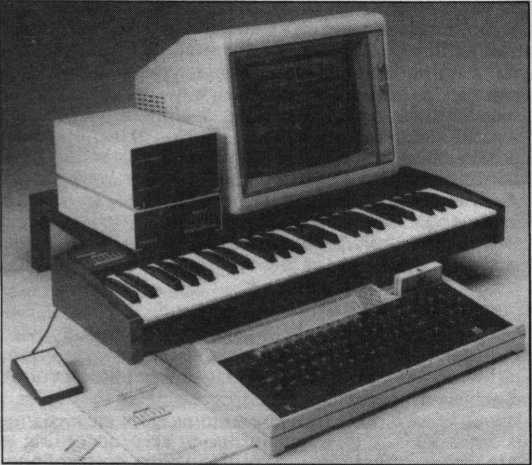
Hybrid Technology's Music 5000 synthesiser for the BBC micro is an amazingly powerful music peripheral for a relatively low cost (see last month's review). It uses exclusively low cost off-the-shelf components as an alternative to the semi-custom and custom devices used in many other modern digital instruments.
To obtain this combination of power and cost-effectiveness, an ingenious and well thought-out design was required.
One of the most important features is the independent control of each channel and voice (collection of channels). In particular, this means that every voice can use a different 'instrument' (overall sound and character). This is essential in a computer music peripheral, in contrast to a keyboard synthesiser where typically only one instrument sound is needed at a time.
Each voice also has separate volume and pan controls so basic mixing desk functions are provided without need for a separate unit, and with full computer control.
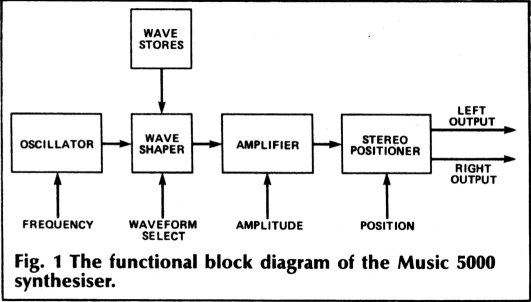
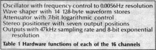
Table 1 summarises the hardware elements of each channel and Fig. 1 shows how they are arranged. All the other voice and channel functions, including pitch conversion, envelopes and modulation are implemented in software on the host computer. We will look at each hardware element in turn.
Oscillator
The oscillator (see Fig. 2) is a 'phase-accumulator' type of digital oscillator. This is analogous to an analogue rampwave oscillator.
Where an analogue oscillator uses a capacitor to determine the phase and a charging current for the frequency, the phase accumulator digital oscillator uses an accumulator and an incrementing value, respectively. The cycle length of the analogue oscillator is determined by a level detect and discharge path. In the digital oscillator this is achieved by the accumulator overflowing.
The accumulator consists of an adder and a register, whose value at any moment is the current phase (the position in the cycle). The increment value is drawn from the frequency register. On each update ('sample') of the oscillator, the frequency is added to the phase, possibly causing the phase to overflow and return to the start of the cycle.
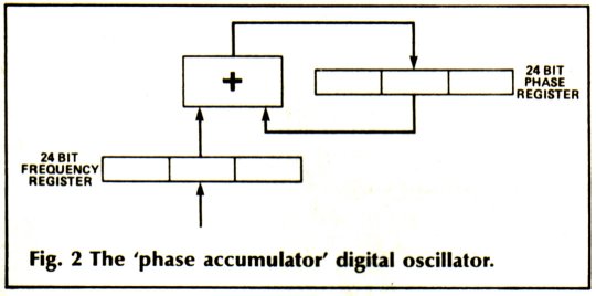
The Music 5000 uses 24-bit frequency and phase words giving very high resolution. Just the top byte of the phase is used as the output so you can think of the complete oscillator a a 16-bit oscillator feeding an 8-bit up-counter, which outputs a ramp wave.
The output frequency is:
One point to note is that a constant frequency resolution is available over the full range - particularly important for fine detuning effects. Cheap computer sound generator ICs use the alternative 'divider' method which gives a frequency resolution that decreases with increasing frequency.
Wave Shaper
The oscillator produces a ramp wave. This is easily converted into any other shape by add ressing a waveform table. Fourteen 128-byte tables in RAM are available, so a 4 bit waveform select and 7-bit oscillator output are combined to address the waveform RAM.
Amplifier
This is the block whose operation is least obvious although its job is quite simple - to allow control over the wave-shaped signal's amplitude by multiplying by a variable value. The direct approach is not on because a digital multiplier IC would be far too costly and so would a DAC with sufficient resolution to handle its output (12 bits minimum).
Our answer is to perform the multiply by the addition of logarithms. In fact, we work in terms of division by an attenuation factor with a minimum of one so the amplitude is always reduced.
log (output) = log (input) - log (attenuation)
output = exp (log (input) - log (attenuation))
We are left with four operations to carry out: add, logarithm (twice) and exponent (anti-log). The add is quite straightforward. The log of the attenuation never needs to be worked out, since the whole system works in logarithmic amplitude control anyway. For example, an envelope decay calculated as a straight line takes
logarithmic shape when played. The log of the input value is calculated by the software, the waveform values being converted to log form on sending to the wave stores.
The final exponentiation is carried out by an exponential DAC, also called an anti-log or 'companding' DAC. This simply produces an analogue output which is the exponent of the digital input.
Stereo Positioner
The final block takes a single signal and divides it between the left and right output channels to determine its stereo position. This extra stage of amplitude control is achieved by very high speed 'chopping' of the analogue signal. In each of six timings slots, each channel is fed either the true signal value or zero, according to a three-bit stereoposition control. When both channels receive the Signal for three slots, the position is central. When one Side gets it for all six slots, the signal is
entirely on that side. Six slots give a convenient total of seven positions.
Outputs
The left and right outputs each have a four-pole low-pass filter which reconstruct the Signals from their sampled and chopped form. Buffer amplifiers present the signal to the connector at the rear of the case. The output level appears to be quite low in normal use. This is because, being a computer controlled synthesiser, a wide range of levels is possible and the gain has been set to make sure the maximum level does not overload the typical hi-fi amplifier DIN input.
Sound Quality
There are three aspects to the sound quality of an all-digital synthesiser:
· output resolution
· dynamic range
· sampling rate
In most cases, the output resolution is simply that of the DAC, typically 8 or 12 bits. In a true synthesiser (not a 'sampler') the full-signal output resolution alone is much less important to overall sound quality than is often believed.
Far more important is the dynamic range or more precisely, how quiet a signal can become before distortion is unacceptable. The problem is that although a resolution of, say, eight bits, can reproduce a full-amplitude signal acceptably, a signal of 1/256th of this amplitude (-48dB) will be converted with 1-bit precision.
The resultant distortion of quiet sounds is unacceptable in a high quality system.
The 'companding' characteristic of the DAC used in the Music 5000 gives the small-signal precision (and therefore a dynamic range) of a 12-bit linear DAC - quite adequate for high-quality synthesis, where no reproduction of recorded sound is necessary.
Since the digital input is still only eight bits, there must be a trade-off at the top of the output range. In fact the precision at the limits is about three percent, roughly equivalent to a 6 bit linear DAC. On a single recorded signal this would give unacceptable distortion ('quantisation noise') but in the Music 5000 each of the 16 channels is converted separately and the effect is merely that you don't get exactly the waveform you ask for.
The last consideration is sampling rate. Again, the effect of this in a synthesiser design is often misunderstood. It has nothing to do with 'sampling' natural sounds but describes the fixed rate at which the synthesiser computes and converts the output signal and hence the fastest changes in the signal that can be reproduced accurately.
The sampling rate sets a limit on the maximum frequency that can be faithfully reproduced. The distortion effect known as 'aliasing' occurs when the frequency exceeds this. With a synthesiser, you expect to be able to play the same sound over a wide pitch range so the design needs a margin of safety on top of the acceptable rate for 'sampling' or recording at comparable quality.
Sampling rate also influences the sound quality through interaction with limited output resolution since a finite sampling rate will cause each step in the waveform to 'jitter' back and forth in the final signal.
You can alternatively think of this as the aliasing of the high frequencies in the steps of the waveform. Either way, the result is noise which may be heard as a 'graininess' in the sound. The Music 5000's high sampling rate of 47kHz minimises noise. Since such noise only occurs along with a sound and not continuously, and it is independent for all channels, its audibility is reduced further by masking.
Implementation
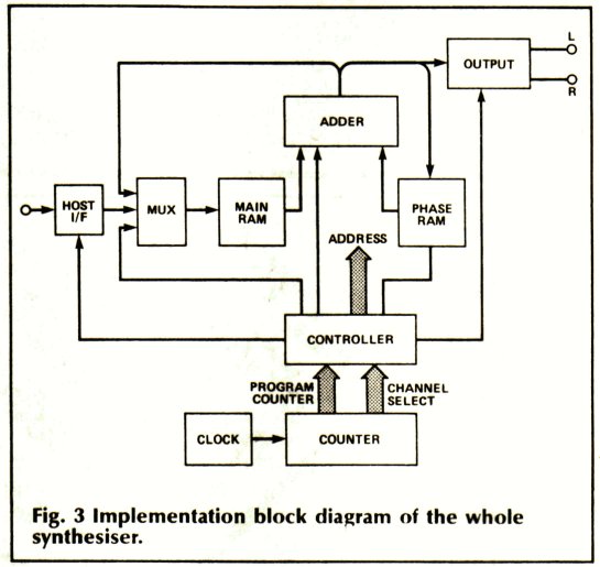
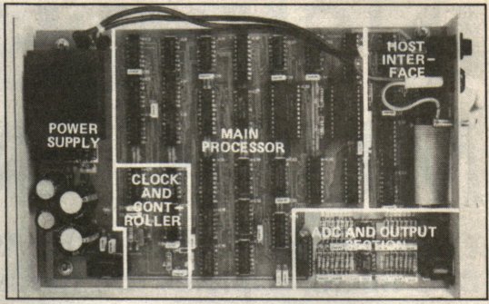
The synthesiser uses a pipelined, fixed-program digital signal processor constructed largely from LS UL devices. It runs at six million instruction cycles per second (requiring 120ns RAM access time) and uses 8-bit data words. The program computes and outputs each channel sample in eight instruction cycles (1.2us), and since there are 16 channels, this gives a total program loop time of 19.2us.
The 12MHz crystal-controlled clock and 8-bit counter generate the 3 bit 'program counter' (instruction number) and the 4 bit channel select. The controller is the site of the 'program' and generates control signals and addresses for all other blocks.
The interface from the host computer (the Beeb) is via a simple bus and is write-only (on the BBC Micro, the synthesiser appears as eight 256 byte pages in the 1MHz bus extended address space). On a write operation, the value is buffered and the DSP transfers it to the internal registers on the first instruction of the next channel loop, that is, within 1.2us.
The 2Kx8 RAM provides the wave stores and those registers to which the host computer has access. A multiplexer supplies its address - from the controller on register instructions, from the buffered register address on the host transfer instruction and from the waveform number and phase (at the ALU output) on the wave-shaping instruction. The frequency is held in three bytes.
The phase RAM holds the phases for all channels (each in three bytes). The frequencies and phases are stored in separate RAMs, each at an input to the adder so that the time-consuming 24 bit oscillator add can be carried out efficiently. The phase RAM is also a 2Kx8 device, so only a small part of it is actually used.
The adder is eight bits wide. It is used by every second instruction in the eight instruction loop, once on the amplifier instruction and once on each of the three oscillator instructions so the 24 bit phase is added in three bytes. A 1-bit register takes the carry from the output to the input and is cleared at the start of each multi-byte add by the controller.
The output block includes the DAC, stereo position chopper and low-pass filters for left and right outputs. It receives the output of the ALU on the amplifier (log add) instruction and the stereo position value.